


Systems Advance for Non-Destructive Evaluation
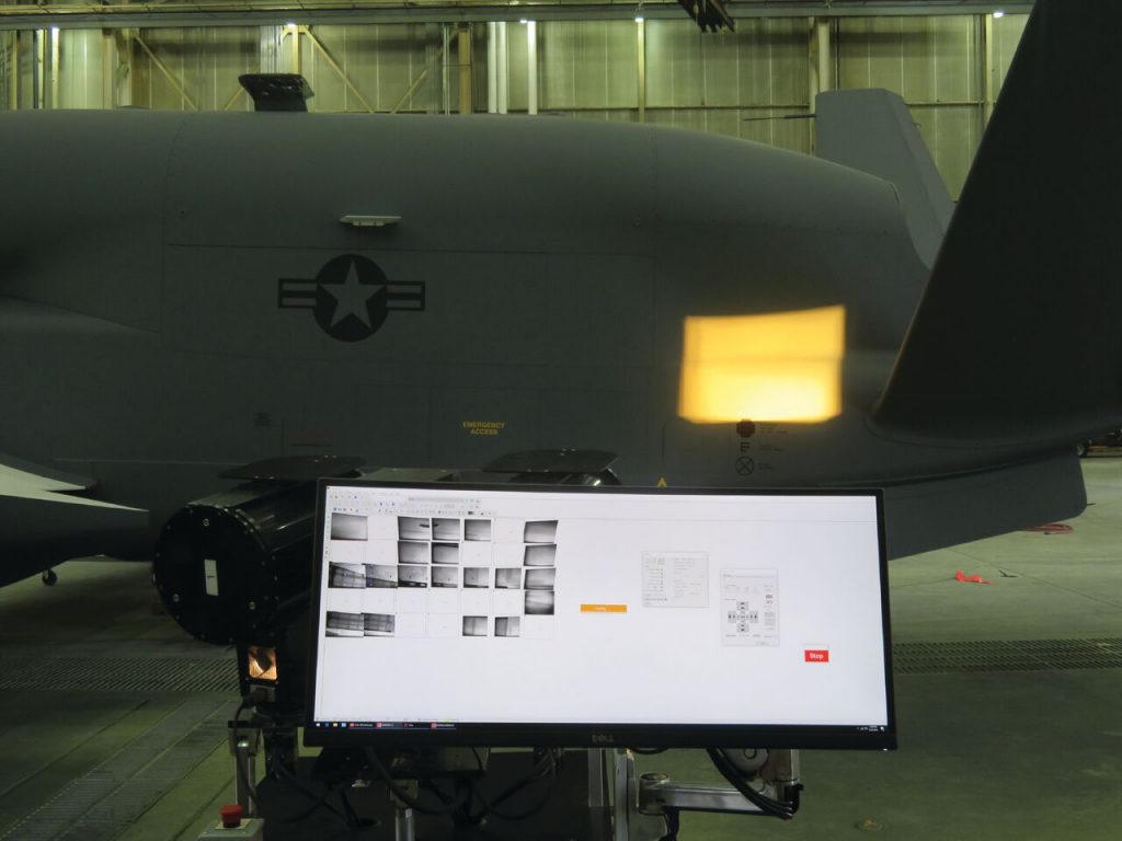
Composites manufacturers are all too familiar with quality challenges. Inclusions and foreign object debris (FOD), incorrect ply orientation, internal voids, porosity, disbonds, delamination and more, both on the surface and interior of composite materials, may result in scrap, rework or worse – failure in the field. Efficient and accurate non-destructive evaluation (NDE) can help manufacturers save time, money and their reputation without cutting apart or altering the composite material. “NDE should be used at various stages of the part’s life cycle – in the development phase, during manufacture of the part, in final factory inspection and when examining the part in the field to identify and assess damage or health and service life longevity,” says Lou Dorworth, direct services manager for Abaris Training Resources Inc., a provider of advanced composites training. Dorworth notes that NDE methods for evaluating composites fall under two main categories – contact (such as traditional ultrasonic) and non-contact testing (thermographic, radiographic, infrared and shearography) – with a few unique technologies sprinkled in, such as acoustic emission testing and electromagnetic testing. “The change [in the NDE landscape] is not so much in the introduction of wholly new technology, rather in the increased capability of existing methods, the sophistication of software and interconnectivity, and the advancement of automation and robotics for conducting evaluations,” says Dorworth. Investing in sophisticated NDE equipment and software may be expensive, but the cost/benefit equation weighs in favor of NDE. Providers of NDE solutions are stepping up with next-generation advancements. Simulated NDE through Cloud Computing “Simulating NDE inspections prior to conducting NDE on a manufactured part can facilitate evaluation in a reduced timeframe and reduce the number and expense of physical tests later on,” says Dorworth. OnScale, founded in 2018, offers a finite element analysis software that conducts scalable ultrasonic simulations using cloud-based high-performance computing (HPC). The software performs ultrasonic modeling and simulations used in a variety of NDE applications to augment real-world data from NDE studies. Cloud-based computing allows for entire inspections to be simulated in parallel to reduce the time frame required for the simulations. OnScale says it is 100 times faster than traditional computer-aided engineering tools. Using OnScale, multi-element arrays can be simulated to generate full inspections without hardware. The rapid simulations assist in eliminating the need for fabricating expensive, bespoke test pieces for pioneering new inspection techniques. In August 2019, OnScale announced a partnership with Eclipse Scientific to network its software with BeamTool 9, an open development software for the design of phased array, time-of-flight diffraction (TOFD) and conventional ultrasonic inspection plans. The user constructs an inspection scenario in BeamTool 9. Using the software to interface with OnScale, the user uploads the scenario problem and parameters to OnScale to perform simulations that model transducers and conduct wave propagation and defect interaction. The simulation results are then downloaded to BeamTool 9 and laid over the BeamTool build model for viewing. Both OnScale and BeamTool 9 are available on-demand as a subscription, so no license is required to use these simulation tools. Laser Systems for In-Process Evaluation “When you are building a laminate, the time to work out structural defects is during lay-up,” says Dorworth. “What I’m looking for are NDE systems to inspect for process flaws in a factory. Laser systems can identify problems such as FOD or misaligned ply orientation that are critical.” This kind of NDE is often underutilized in the composites industry, he adds. Aligned Vision is the maker of LASERVISION, a laser guidance technology combined with an aimed vision system for in-process NDE that draws comparative information directly from the part’s design data. According to Scott Blake, president of Aligned Vision, quantitative automatic in-process inspection may help composites manufacturers lessen the overdesign required to address manufacturing variation and uncertainty. Lessening overdesign may, in turn, reduce material usage, process time, part weight and cost. First, LASERVISION’s laser projector delivers design data to the tool or work surface via laser templates rather than traditional templates. A template of light helps the worker to lay down precut material precisely by identifying edge locations and correct fiber orientation. Next, the aimed vision system (camera), which is connected to the laser projector, captures and automatically analyzes build data to optically check three parameters: the presence and location of each piece of material, the fiber orientation of the material and the absence of FOD. “We’re guiding the assembly, we’re checking it against a digital template during the build process, and we’re directing the operator to any suspect areas,” says Blake. For example, if a fiber orientation is incorrect, the system sends the message “incorrect fiber orientation” and won’t proceed with the laser template for the next ply. “The result is less rework and scrap, enabling the manufacturer to make corrections at the earliest possible stage,” says Blake. “Customers have complete traceability through a database of data and imagery for the inspected areas.” In a previous generation of the system, a handheld camera system was placed at the inspection location, guided by the laser. The new generation LASERVISION inspects the material placement from a mounted system. “The wing skins of Boeing’s 777X are our largest application at 100 feet long and 20 feet wide at the root,” says Blake. “We view the material as it is placed by an automatic fiber placement robot. With our software, interconnectivity enables our LASERVISION system to stop the process of a robotically built part if the variation is unacceptable.” Blake notes that inspection time is reduced and the potential for human error is replaced with computer-driven analysis and accuracy. “We have found problems that our customers did not even know they had,” he says. “We were able to prevent some potential part failures.” Blake believes future applications will incorporate artificial intelligence and deep learning to build and analyze images captured by LASERVISION to create “classifiers” of good and bad parts. “Using deep learning fed by the thousands of images we’re now creating, resulting algorithms will help LASERVISION reliably recognize if the image it is fed is acceptable or unacceptable,” he says. “Composite parts manufacturers will be able to use the images collected by LASERVISION to apply feature recognition and statistical processing to improve automated inspection even further.” Next-Generation Ultrasonics According to a peer-reviewed study of non-destructive testing methods for composites materials by Saeed Gholizadeh, (Structural Integrity Procedia 1 (2016) 050-057), ultrasonic testing – whether pulse echo or through transmission – is still one of the best methods to analyze composite parts. Classic ultrasound techniques require a composite part to be immersed in fluid, such as water or gel, which is restrictive when evaluating large parts. Newer methods of ultrasound evaluation include dry and non-contact approaches that take images without loss of signal strength. “DolphiCam is an ultrasound NDE system with a dry, silicone-rubber stand-off nose at the end of the probe. It does not require a coupling agent. The operator simply walks up to the part, compresses the nose to the part and takes the image,” says Dorworth. “When I was first introduced to DolphiCam, I plugged in the software, plugged in the instrument and a standard, and started inspecting, receiving green ‘go’ messages or red ‘defect’ messages within minutes.” Another alternative to “wet” ultrasound comes from the Ultran Group. Ultran offers non-contact ultrasound systems particularly for porous structures or structures incorporating honeycombs or cells. The technology increases the efficiency of its transducers through a proprietary gas matrix piezoelectric (GMP) material for a non-contact environment. Most recently, the company has optimized its ultrasound NDE system to support large and complex structures and very attenuated products, such as rocket payload fairings. Ultran’s latest applications incorporate interconnectivity and networking to partner with systems integrators. These partners bring robotics and multi-axis scanning capability to the projects. “We fit the non-contact ultrasound system on the robot and establish a protocol to speak to the robot’s motion controller,” says Michael Whetzel, COO of the Ultran Group.” We must be aware of cable locations and deal with electrical noise from the robot’s motors while still maximizing acquisition of the data. There’s no standard protocol, and so each time, we work with the system integrator to either transmit our data to the robot controller or to use our software to present the data to the customer in a way that is easy for them to interpret.” Whetzel says the Ultran Group is one generation away from standardizing a communications protocol, however there aren’t enough projects to require that just yet. Like Blake of Aligned Vision, Whetzel views big data as the key to refining the composites industry’s approach to defining a defect. “Right now, ultrasound can identify a part that is not uniform, but it can’t tell you whether that constitutes a defect. The customer must correlate non-uniformities and variation to interpret whether it is a defect in their world,” says Whetzel. “I believe that in the future, big data will automate the determination of defects so that a technician isn’t required.” For now, says Whetzel, most one-off composite parts are constantly changing so there’s not enough data yet, especially in aerospace and rocket applications. But the automotive industry has volumes, which can facilitate data analytics in the future. “That will lead to closed-loop manufacturing that can detect and correct the process when it falls out of specification limits,” says Whetzel. State-of-the-Art Thermography While many NDE methods require the evaluation equipment to be close to or touching the part, Thermal Wave Imaging Inc. departs from that model with its Large-Standoff, Large-Area Thermography (LASLAT) system, which performs NDE of large composite structures using projection thermography and high-resolution cameras. LASLAT operates at a 10- to 15-foot standoff distance from the part being inspected at rates as high as 8-square-feet per minute, depending on the material and minimum defect size requirement. Instead of moving the instrument along the body of the large part with a robot, gantry or drone, LASLAT is set in one position and its beam is automatically scanned over the target surface. At each defined subsection, the scan stops, projects heat via light and measures the rate of cooling to identify issues such as delamination, impact damage or water entrapment. “LASLAT streamlines the inspection process so that time spent on ancillary tasks – such as positioning, marking and archiving – is reduced or eliminated,” says Steven Shepard, president of Thermal Wave Imaging. “It can be moved to different inspection stations for different applications, unlike fixed gantry or robotics, which are considerably more expensive. The inspector has more time to analyze the problem.” The first LASLAT system, developed for the Naval Air Systems Command (NAVAIR), was delivered in 2018 to a Fleet Readiness Center in Cherry Point, N.C., to improve detection capabilities for V-22 proprotor blade inspections. Thermal Wave was recently awarded a Small Business Innovation Research Phase II.5 contract from NAVAIR’s Fleet Readiness Center in North Island, Calif., to improve detection capabilities for aircraft structures on the E-2 and F-18 platforms. LASLAT is now available commercially. Embedded Sensor Technology It would be great if wind turbine blades or aircraft wings could alert you when they had a problem. Embedded sensors offer a step in that direction. One such NDE method is the ODiSI 6000 Series, a fiber optic sensor system from the Lightwave Division of Luna that can profile temperature in-situ, measure 2D and 3D strain fields to validate FEA models and evaluate multi-material joining. Fiber optics are flexible, low profile, require no electrical source and are able to be embedded into or bonded onto any part geometry where other sensors cannot – in bends and around corners. The optical fiber itself is a non-intrusive wire-length silica that is approximately .15 millimeters in diameter. The ODiSI 6000 system provides more than 150,000 measurement locations with 1,000 strain or temperature measurements per meter, providing high-definition data that can be used to map the contour of strain or temperature for a structure being tested, according to Luna. “When a part is in service, we can remotely see damage as a function of a change in the strain signal,” says Matt Davis, R&D director for the Lightwave Division of Luna. Depending on the needs of the customer, ODiSI 6000 can be deployed for continuous monitoring via a network that sends data to a larger data management system. Or it can be used in the field for periodic inspections. According to Davis, the part data in its current state is compared to a historic record of the part within the customer’s quality control infrastructure. The software will recognize the part once the ODiSI is connected and then collect the data to determine if there has been a material change. Davis says the area of measurement can reach up to approximately 150 feet, making it ideal for identifying the horizontal and vertical location of material changes in large parts. Visualization software color maps the magnitude of measurement to the location of the fibers. As an example, bright red indicates load tension while bright blue typically shows areas of compression. So, a strike might show blue where the hit was and red surrounding it, depending on the part geometry. The user can adjust the color scale to identify what they are most interested in identifying. These advances in NDE – and others on the horizon – take advantage of technological innovations and show promise for the composites industry. “These new methods of performing NDE to revise design, to make corrections to the manufacturing process and to analyze parts in the field are often headed for use in Industry 4.0 platforms,” says Dorworth. “It’s quite interesting to see how these advancements in NDE are reducing problems for the FRP industry.”

Your source for composite reinforcements & technical support
Vectorply combines highly engineered composite reinforcements w/ industry-leading engineering & technical support to help customers achieve their production goals.
Meet the LSAM Additive Printer
A lower-cost “print only” line of machines built around proven LSAM technology

SUBSCRIBE TO CM MAGAZINE
Composites Manufacturing Magazine is the official publication of the American Composites Manufacturers Association. Subscribe to get a free annual subscription to Composites Manufacturing Magazine and receive composites industry insights you can’t get anywhere else.